20W 95db Outdoor GSM DCS Dual Band Repeater BDA
We can also make other dual band repeater as customer,feel free to contact us for your requirement!
Introduction
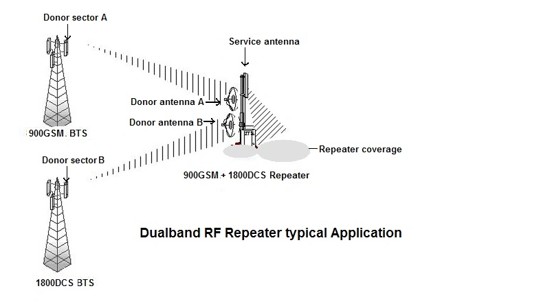
RF Repeater is designed to enhance cellular network coverage and fill blind spots. Main operation of the repeater
is to receive low-power signal from Base Station (BS) via radio frequency (RF) transmission by its donor antenna,
process, amplify and forward the signal to Mobile Station (MS) in target coverage area by its service antenna.
Features
1.Aluminum alloy enclosure for excellent heat dissipation,waterproof design for all-weather installation;
2.Metal cavity filter technology inside, which gives wider receiving and sending separation, better gain flatness, higher stability, and lower noise figure;
3.Modules structure,full-duplex & dual-port design, and built-in power supply,easy for maintenance and installation;
4.High linearity PA; high system gain;
5.Allowing for continuous gain adjustment 31dB by 1dB step;
6.ALC technology used to provide auto amplitude fixing;
7.Press-key , Local PC GUI operation and Optional Remote Modem control.
RF Repeater Typical Application

Specifications
Schematic

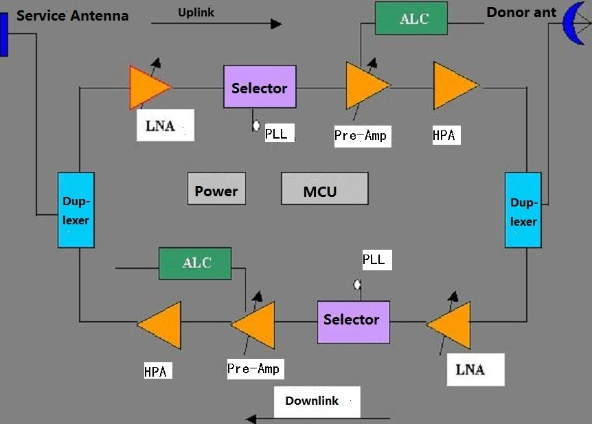
Working principle:
When the repeat antenna receives uplink signals from a subscriber, the signals will undergo processing of low-noise amplifier, filter and power amplifier first, and then be transmitted to the base station, thus accomplishing connection between subscribers in signal blind area and base station.
In this way, the blind areas are eliminated.
Considering receiving signal intensity and coverage size may vary with sites where repeater is located, it is necessary to control the gain and output of the repeater.
Additionally, considering the fading effect in spatial signal transmission, auto amplitude fixing for output is required.
For this purpose, MGC and ALC circuits are included in the uplink/downlink channels.
Site Survey
Before you install, the installer should contact the person responsible for the project, understand whether there are installed conditions in the installation site.
Specifically include: Installation site, surroundings (Temperature and Humidity), power supply, and so on. If qualified, should go live on-site survey with related personnel. The repeater is designed that can working outdoors, operating temperature is -25ºC~65ºC, humidity is ≤95%, which can be adapted to most areas of the natural environment.
Recommended Environmental Requirements:
1.Installation area non-corrosive gases and fumes, Electromagnetic interference field strength ≤140dBμV/m(0.01MHz~110000MHz).
2.Mounting height should facilitate the RF cable routing, cooling, safety and maintenance.
3.Should provide a set of independent and stable 150VAC~290VAC(Nominal 220V/50Hz)AC Power. It must not be shared with other high-power appliances telecommunications equipment.
4.Lightning protection devices must be installed in the building, and it should have sufficient strength and stability.
5.There are grounding bar in the vicinity.
Installation Tools
Installation tool to use: Electric impact drill, iron hammer, pulleys, ropes, belts, helmets, ladders, screwdriver, hacksaw, knife, pliers, wrenches, compass, measuring tape, tweezers, electric iron, portable PC, 30dB directional coupler, spectrum analyzers, VSWR tester.
Repeater installation
It can be holding pole or wall mounting way. It should be installed in ventilated place, vertically on a wall or mast to ensure good heat dissipation, if hang on the wall, the upper part of the equipment to be considered more than 50cm from the ceiling, the lower part of the equipment needs more than 100cm from the floor.
Antenna and Feeder Installation and Precautions
1.Installation of antenna systems requires experienced professionals to complete.
2.You can not install an antenna near power lines, which may be life-threatening.
3.All exposed joints must use self-adhesive waterproof tape and electrical insulation tape seal securely.
Connect the Ground and Power Supply
1. Equipment Grounding
The equipment must be well grounded, there is a copper on the repeater wall chassis ground, use 4mm2 or thicker copper wire close to the ground. Grounding wire should be as short as possible. When installed, the equipment grounding wire should be connect to the integrated grounding bar. Grounding resistance of requirements bar may be≤ 5Ω, ground connector require preservative treatment.
2. Connect the Power
Connect 220V/50Hz AC power to the equipment power port terminal blocks, power line use 2mm2 cables, length less than 30m. For standby power requirement, the power must go through UPS, and then connect the UPS to the repeater power port terminal blocks.
For more details,feel free to contact us!
We can also make other dual band repeater as customer,feel free to contact us for your requirement!
Introduction
RF Repeater is designed to enhance cellular network coverage and fill blind spots. Main operation of the repeater
is to receive low-power signal from Base Station (BS) via radio frequency (RF) transmission by its donor antenna,
process, amplify and forward the signal to Mobile Station (MS) in target coverage area by its service antenna.
Features
1.Aluminum alloy enclosure for excellent heat dissipation,waterproof design for all-weather installation;
2.Metal cavity filter technology inside, which gives wider receiving and sending separation, better gain flatness, higher stability, and lower noise figure;
3.Modules structure,full-duplex & dual-port design, and built-in power supply,easy for maintenance and installation;
4.High linearity PA; high system gain;
5.Allowing for continuous gain adjustment 31dB by 1dB step;
6.ALC technology used to provide auto amplitude fixing;
7.Press-key , Local PC GUI operation and Optional Remote Modem control.
RF Repeater Typical Application

Specifications
| Project | Uplink | Downlink | |
| Working Frequency | GSM900 | 880 ~ 915 MHz | 935 ~ 960 MHz |
| DCS | 1710 ~ 1785 MHz | 1805 ~ 1880 MHz | |
| Frequency Error | ≤±0.5ppm | ||
| Output Power | 33dBm | 40dBm | |
| Gain | 85dB | 90dB | |
| In-Band Ripple | GSM | ≤3dB | |
| DCS | ≤5dB | ||
| WCDMA | ≤5dB | ||
| VSWR | ≤1.5:1 | ||
| Three order intermodulation | ≤-45dBc/30KHz | ||
| Gain adjustment accuracy | 0-10dB≤1dB | ||
| 10-20dB≤1dB | |||
| 20-30dB≤1.5dB | |||
| System Delay | ≤1.5us | ||
| Rejection band | Fo±0.4MHz | ≤-25dBm | |
| Fo±0.6MHz | ≤-35dBm | ||
| Fo±1MHz | ≤-48dBm | ||
| Spurious Emission | 9KHz~150KHz≤-36dBm/10KHz | ||
| 150KHz~30MHz≤-36dBm/100KHz | |||
| 30MHz~1GHz≤-36dBm/100KHz | |||
| 1GHz-12.75GHz≤-30dBm/1MKHz | |||
| Noise Figure | ≤5dB | ||
| I/O Impedance | 50Ω | ||
| RF Connector | N-Type (Female) | ||
| Frequency error | ≤±5×10¯8 | ||
| Radio Equipment Directive | 2014/53/EU | ||
| Electromagnetic compatibility | To the ETSI EN 301 489-1 V2.2.0, ETSI EN 301 489-3 V2.1.1 standard | ||
| Power | AC110V or AC220V | ||
| Temperature Range | -25ºC~+65ºC | ||
| Relative humidity | ≤95% | ||
| Size | 540X360X230mm | ||
| Weight | 25kg | ||
| Operation Configuration | LCD Display, Manual Key-press, PC RS232 Port | ||
| GSM MODEM (Optional) | |||
| Ethernet RJ45 (Optional) | |||
Schematic

Working principle:
When the repeat antenna receives uplink signals from a subscriber, the signals will undergo processing of low-noise amplifier, filter and power amplifier first, and then be transmitted to the base station, thus accomplishing connection between subscribers in signal blind area and base station.
In this way, the blind areas are eliminated.
Considering receiving signal intensity and coverage size may vary with sites where repeater is located, it is necessary to control the gain and output of the repeater.
Additionally, considering the fading effect in spatial signal transmission, auto amplitude fixing for output is required.
For this purpose, MGC and ALC circuits are included in the uplink/downlink channels.
Site Survey
Before you install, the installer should contact the person responsible for the project, understand whether there are installed conditions in the installation site.
Specifically include: Installation site, surroundings (Temperature and Humidity), power supply, and so on. If qualified, should go live on-site survey with related personnel. The repeater is designed that can working outdoors, operating temperature is -25ºC~65ºC, humidity is ≤95%, which can be adapted to most areas of the natural environment.
Recommended Environmental Requirements:
1.Installation area non-corrosive gases and fumes, Electromagnetic interference field strength ≤140dBμV/m(0.01MHz~110000MHz).
2.Mounting height should facilitate the RF cable routing, cooling, safety and maintenance.
3.Should provide a set of independent and stable 150VAC~290VAC(Nominal 220V/50Hz)AC Power. It must not be shared with other high-power appliances telecommunications equipment.
4.Lightning protection devices must be installed in the building, and it should have sufficient strength and stability.
5.There are grounding bar in the vicinity.
Installation Tools
Installation tool to use: Electric impact drill, iron hammer, pulleys, ropes, belts, helmets, ladders, screwdriver, hacksaw, knife, pliers, wrenches, compass, measuring tape, tweezers, electric iron, portable PC, 30dB directional coupler, spectrum analyzers, VSWR tester.
Repeater installation
It can be holding pole or wall mounting way. It should be installed in ventilated place, vertically on a wall or mast to ensure good heat dissipation, if hang on the wall, the upper part of the equipment to be considered more than 50cm from the ceiling, the lower part of the equipment needs more than 100cm from the floor.
Antenna and Feeder Installation and Precautions
1.Installation of antenna systems requires experienced professionals to complete.
2.You can not install an antenna near power lines, which may be life-threatening.
3.All exposed joints must use self-adhesive waterproof tape and electrical insulation tape seal securely.
Connect the Ground and Power Supply
1. Equipment Grounding
The equipment must be well grounded, there is a copper on the repeater wall chassis ground, use 4mm2 or thicker copper wire close to the ground. Grounding wire should be as short as possible. When installed, the equipment grounding wire should be connect to the integrated grounding bar. Grounding resistance of requirements bar may be≤ 5Ω, ground connector require preservative treatment.
2. Connect the Power
Connect 220V/50Hz AC power to the equipment power port terminal blocks, power line use 2mm2 cables, length less than 30m. For standby power requirement, the power must go through UPS, and then connect the UPS to the repeater power port terminal blocks.
For more details,feel free to contact us!