TETRA 400MGHz ICS Repeater
Model: BT-7A40S
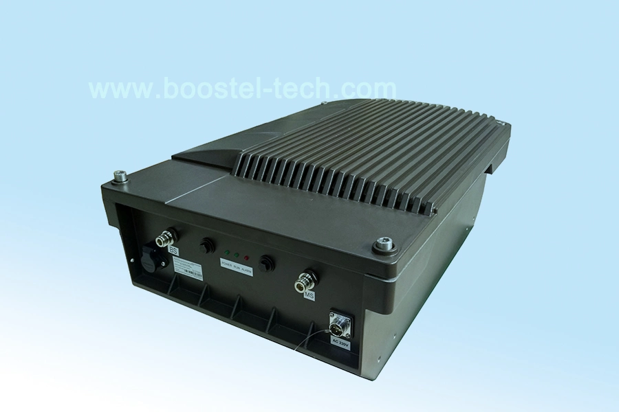
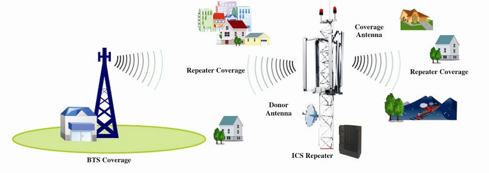
The ICS Repeater is designed to provide a more cost-effective solution than adding a new Base Transceiver Station (BTS) to improve signal coverage and communication quality in GSM/DCS/PCS system. And its easy installation and maintenance can help carriers get fast return.The repeater is working as a relay between the BTS and mobiles. It receives the low-power signal from BTS via the Donor Antenna, linearly amplifies the signal and then retransmits it via the Coverage Antenna to the weak/blind coverage area. And the mobile signal is also amplified and retransmitted to the BTS via the opposite direction.Model: BT-7A40S
Features |
Aluminum-alloy casing with IP65 protection has high resistance to dust, water and corroding
No interference to BTS by adopting linear amplifier with high gain and low noise
Adopting filter with highly selectivity and low insertion loss eliminates interference between uplink and downlink
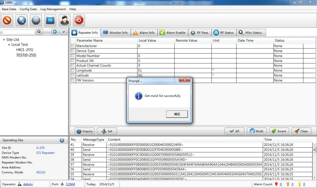
USB port provides a link to a notebook for local supervision or to the built-in wireless modem to communicate with the NMS (Network Management System) that can remotely supervise repeater's working status and download operational parameters to the repeater
Applications
To expand signal coverage or fill signal blind area where signal is weak or unavailable.
| Outdoor: | Airports, tourism regions, golf courses, tunnels, factories, mining districts, villages, … |
| Indoor: | Hotels, exhibition centers, basements, shopping malls, offices, parking lots, … |
Application Diagram |
Technical Specifications
| Items | Specification | |
| Working Frequency (Customized) | Uplink | TETRA 400MHz |
| Downlink | TETRA 400MHz | |
| Maximum Output power(Customized) | 30/33/37/40/43dBm | |
| Maximum Gain | 100dB | |
| Gain Adjustment Range | 1~31 dB @ step of 1 dB | |
| Operating Maximum Gain | ≥ Antenna Isolation + 10dB | |
| No. of Channels | 12 | |
| Power Amplifier Oscillation Protection | Interference Cancellation System | |
| Cancellation Feedback Signals - Maximum Sizes of Window | ≥ 6μSec | |
| Interference Cancellation Range | ≥ 25dB | |
| Frequency Error | ≤ 0.05ppm | |
| Voltage Standing Wave Ratio | ≤ 1.5 | |
| Noise Figure | ≤ 6dB | |
| In-band Ripple | ≤ 3dB | |
| Max. Input Level | ≥ -10dBm | |
| Spurious Emission | ≤ -36dBm | |
| Third-order Inter-modulation | ≤ -45dBc/30KHz(measured under rated output power) | |
| System Delay | ≤ 5.0μSec | |
| I/O Impedance | 50Ω | |
| RF Connector | N-Type (Female) | |
| Temperature Range | Operation: -25°C ~ + 55°C / Storage: -30°C ~ +60°C | |
| Relative Humidity Range | ≤ 95% (non condensing) | |
| Environment Class | IP65 | |
| Dimensions | 610mm X 445mm X 215mm | |
| Weight | ≤ 35Kg | |
| Power Supply (customized) | DC-48V or AC110V or AC220V,50/60Hz | |
| Backup Power Supply (optional) | 4 hours | |
| NMS Monitoring Parameters(optional) | UL/DL Power, UL/DL Max Gain, RSSI, ATT, Channel No, UL/DL Output ALC, Power alarm Threshold, UL/DL PA Temperature etc | |
| NMS Controlled Parameters(optional) | Channel No., ATT, Output Power Thresholds UL/DL, UL/DL Output ALC , PA Switch ,Alarm Report can be enable /disable etc | |
Installation & Commissioning
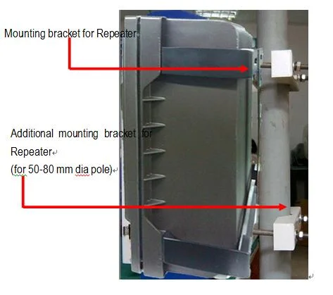

Figure3 Interface of NMS Board
1.1 Installation
- At the installation site, install the repeater as per specified plan and site layout. The repeater can be wall-mounted or pole-mounted using the brackets as shown below.
2. Connect the repeater to the grounding board.
3. Install the Donor Antenna and Coverage Antenna as per the specified plan and site layout.
4. Use Site Master to measure the VSWR of the RF cables from the Donor Antenna and Coverage Antenna. The value should be less than 1.5; Otherwise, check the connectors and the installation of the cable.
5. Connect the power supply (and backup power if required) to the repeater.
6. Start commissioning the repeater.
1.2 Commissioning
- Connect the RF cable from Donor Antenna to the spectrum analyzer and check if the Donor Antenna is receiving the correct frequency; and then measure the signal level of the said frequency (RSL). Adjust the antenna to make the readings approach the recorded value on the survey report. Record all readings.
- Inside the repeater, disconnect the uplink duplexer to the ICS module so as to cut any signal coming from air going to the uplink duplexer and thus protecting the amplifier from damaging. Connect a 30 dB attenuator to the output of the repeater; this attenuator will serve as a load for the repeater. The purpose of this attenuator is to protect the equipments from damaging.
- Turn ON the repeater. Observe the LED display on the NMS board. Check for any alarm. Under normal condition, the POWER LED should be always green and the RUN LED should be blinking, the ALARM LED should be not bright with red color.
Figure3 Interface of NMS Board
Connect your laptop to the repeater via the data cable.